
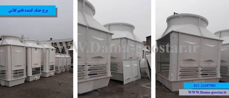
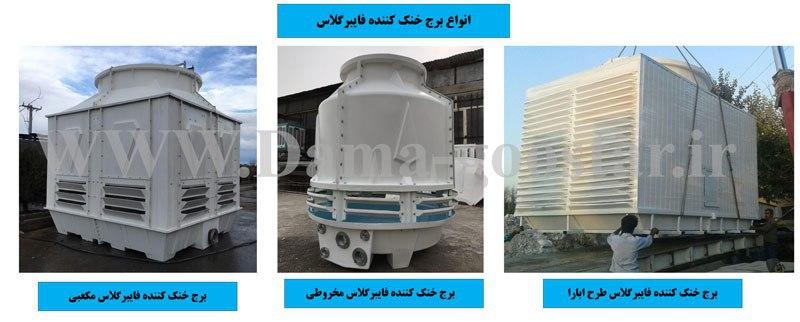
Fiberglass cooling tower is a type of cooling tower or cooling tower with a composite or fiberglass body. Fiberglass cooling tower is a source of hot water cooling returned from chillers or industrial machines. Fiberglass cooling tower is a water-to-air cooling converter that has different types. The hot water in this equipment is cooled by the outside air. Excess heat is discharged from the top of the fiberglass cooling tower. The cooled water in the fiberglass cooling tower drops to a humid temperature. As a result of the contact process, the air in the cooling tower evaporates. Evaporation of water increases the humidity of the exhaust air. The vapors released from the water are directed to the open air as moisture. There are different types of fiberglass cooling towers, the most common of which are cubic fiberglass towers and open circuit cones.
You may ask, what is fiberglass?
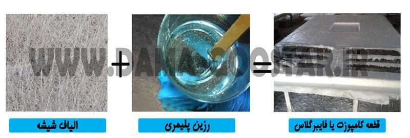
Fiberglass is a type of composite or a combination of several different polymeric materials (resin and adhesive) with glass. Fiberglass is named after two words, fiber (compressed plastic) and glass, and means a combination of polymer and glass. Fiberglass is classified into two categories, frp and grp, which frp stands for fiber reinforced polymer. Fiberglass is composed of a combination of glass fiber and special adhesive (resin) and is much stronger than other polymers due to its composite structure.
Simply put: fiberglass is a type of polymer that is reinforced by glass fibers and has a very high mechanical strength.
Why do we use fiberglass in the structure of the cooling tower ???
At this stage, one may ask why most of the cooling tower products are offered with fiberglass body today. In response to this issue, we must say that there are many reasons for the use of fiberglass in the structure of the cooling tower body, the most important of which are:
No rusting of the body in response to moisture and water
Impermeable to the heat of the sun (especially in summer)
Anti-UV body and no sunburn and rot of parts against sunlight
Possibility of production and manufacturing in very large capacities in a multicellular manner
Extremely low fouling against solutes in water
Lightweight fiberglass structure compared to different metals and concrete
Low vibration and vibration of the body due to bolts and joints of the body
The growth of algae and bacteria in the fiberglass environment is slow.
Very long life of fiberglass body in the useful life of the cooling tower
Cheaper production and high economic efficiency
Build faster
Easy to move and carry
To what temperature does the fiberglass cooling tower reduce water?
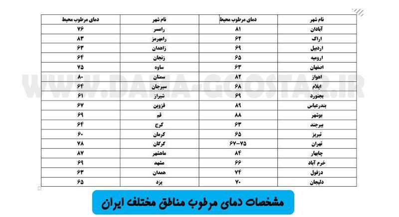
The combination of humidity with ambient air causes the air to reach a state of saturation (humidity 100). Water also decreases to near humid ambient temperature due to the above in the fiberglass cooling tower. Wet bubble temperatures or saturation temperatures of different regions and different climates are very different from each other. In environments that are adjacent to the sea or lake, such as the southern and northern coasts of the country, the relative humidity of the environment is high. Increasing the humidity of the environment will increase the temperature of saturated air, and as a result, the outlet water of the cooling tower will have a higher temperature. In other words, the humid air is very different in different parts of the country and the cooling tower has different functions in different parts. All types of fiberglass cooling towers can reduce the water temperature to 3 degrees above ambient temperature.
More information about Wetball temperature and design conditions in: Cooling tower calculations
Conclusion: In designing and selecting fiberglass cooling tower, considering the climatic environment conditions (temperature, humidity, etc.) is very important and vital.
*** The image below shows the humid temperature limits of different regions of Iran in the summer heat peak (August).
In this type of use, fiberglass cooling towers generally use white circular cooling towers on the roofs of buildings. The function of the fiberglass cooler tower is to cool the water of the chiller condenser in the engine room. Chiller cooling tower is often more used than industrial use. Increasing number of central air conditioning systems in buildings leads to more use of cooling towers in this use. Fiberglass or composite towers are sometimes disassembled. If a building cannot accommodate this equipment, the fiberglass cooling tower will be dismantled and assembled on site.
More details: Chiller cooling tower
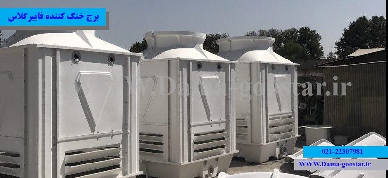
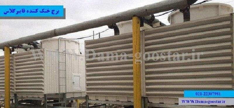
In the industrial use of the cooling tower with fiberglass body, this equipment has been very popular in various industries today. Due to the high performance and efficiency of fiberglass cooling tower, today in most industries, various types of fiberglass cooling towers with cubic or rectangular structure are used. Refrigeration modulating systems are widely used due to industrial conditions in the country. Today, the manufacturing industry is more active than ever compared to the active construction industry. In the production industry, the most important principle is uninterrupted production. One of the advantages of fiberglass cooling tower is easy and convenient maintenance. Using this advantage, the production industry will continue to operate with the highest efficiency.
More details: Industrial cooling tower
Water cooling by heat transfer:
The water that is cooled in the fiberglass cooling tower by the cold air outside loses heat in two basic ways. The first method is due to the difference in temperature of hot water with the outside air, which is called refrigeration heat transfer. Due to the phenomenon of cryogenic heat transfer in the fiberglass cooling tower, the water is cooled according to the amount of aeration and the size of the ambient temperature. The more volume of air we can put in contact with water, the greater the amount of refrigeration transfer. In many cases, in hot seasons, this amount decreases with increasing dry temperature and approaching ambient temperature to hot water temperature.
Water cooling by sensible heat transfer:
The second method in reducing the water temperature in fiberglass cooling tower is evaporation and release of noticeable heat of water. In fact, to evaporate a percentage of hot water flow, heat is needed, and this tangible heat is taken from the water flow itself. After evaporation, water enters the dry air in the form of vapors and saturates. The lower the humidity, the more noticeable heat is taken from the water and the cooler the water. Due to this, the performance of fiberglass cooling tower is better in dry environments (with low humidity). Perceived heat is always greater than the amount of heat that is transferred based on the difference in temperature of the climate.
Panels The main walls of a fiberglass body are cooling towers. Panels can be modularly connected to other sections to form the final frame.
A column is attached to the panels on one side and to the base and Louvre on the other. The main weight of the fan deck or fan stack is divided by a column on the structure.
The basin is located at the bottom of the cooling tower. Cold water collects in the pan or basin after passing through the packings. This cold water collected by the circulator pump enters the cooling circuit.
The Louvre is located on the air inlet in the form of a blade. The suction air of the fan is directed through these valves into the cooling tower. Louvres typically use two types of honeycombs or blades in a cooling tower.
The fan outlet throat is placed in the form of a chimney-like compartment at the top. The hot and saturated air from this section is directed to the outside environment. The fan deck is located in the form of a divergent cone at the top of the tower.
The new generation is the production of fibrous or composite parts of the Paltrogen process. Paltrogenic parts are produced in the form of cans or corners of fiberglass and resin materials (fiberglass). These parts have replaced the metal supports in the cooling tower.
Fiberglass refrigeration systems in a general classification are divided into two subgroups, open circuit and closed circuit. CCTV refrigeration systems are divided into two categories, hybrid and dry, depending on the type of use. CCTV towers have less water consumption or no water consumption at all compared to the open type. Evaporation does not occur in fiberglass coolers due to air contact with water under the contact surface (coil). CCTV systems cool water without evaporation and sedimentation, and open circuit systems cool water by generating steam. Lack of sediment layers in condenser converters of exothermic equipment is one of the most important advantages of CCTV cooling towers.
Open circuit fiberglass cooling tower is divided into two categories of opposite and cross current. The appearance of the cross-flow cooling tower is cross-shaped rectangular. The countercurrent model is also produced in cube or round. Cubic models are more useful due to their optimal water distribution system and high efficiency. Chilled water in cubic refrigeration systems is reduced to a lower temperature due to its higher altitude. The temperature of the cold water leaving the cube fiberglass cooling tower is three degrees higher than the ambient wetting temperature. In circular systems, the temperature of cold water decreases by about 5 degrees above the saturation temperature of the environment.
Briefly, we can describe the classification of fiberglass cooling tower as follows.
A) Open circuit type fiberglass cooling tower
B) Fiberglass cooling tower of dry circuit type
C) Fiberglass cooling tower type hybrid CCTV
first stage:
Molding of fiberglass body parts
The most basic stage of cooling tower production is the construction of body parts. The fiberglass body of the cooling tower, as mentioned, has different components. The various components of the fiberglass body are produced separately in the initial stage by molding. Each fiberglass component has a specific mold and size.
second stage:
Polishing and baking fiberglass body parts
After the molding stage, we separate the body parts from the mold. We expose the fiberglass parts of the cooling tower to sunlight for a certain period of time. Sunlight causes the resin to cure and solidify in the inner fiberglass texture. After completing the cooking process, the body parts of the cooling tower are polished by sunlight.
third level:
Production of metal parts of cooling towers by turning machines
The metal components of the cooling tower include speed reduction - fan or impeller - sprinkler and engine and fan retaining parts. Metal components are each produced by turning and casting machines. The process of molding, casting, turning and balancing are the main stages of making this part.
Step 4:
Production of plastic parts by injection machine or extruder
Cooling tower plastic or polymer components include nozzles, drippers, tubes, belt clamps and media packing. Each of these polymer parts is produced in specific molds by plastic injection machines. Some plastic parts are produced in the form of polymer sheets. These sheets are attached to another molding machine by a pin or adhesive connection. After connecting the sheets, the dripper and packing are used as a block inside the cooling tower.
Step 5:
Assembling and assembling parts together
This stage is the final part of the production of fiberglass cooling towers. Assembling or assembling parts together requires an explosive plan. Explosive drawings of the machine are usually provided to the production unit before the assembly process. The production and assembly unit assembles the device according to the explosive plan. The final assembly of the cooling tower can be done at the factory or at the project site.
The main reason for naming this refrigeration machine is the composite structure of the body parts. Fiberglass (FRP) is basically an abbreviation for Fiber Resistance Polymer. FRP fiberglass means a polymer-resistant glass fiber or structure. The fiberglass body used in the cooling tower is a body reinforced with glass fibers and polymers or resins. Resin is the main adhesive-like texture in composite parts. Resins are used as polymers in this compound. Fiberglass also strengthens the fiberglass composition in the cooling tower. The combination of fiberglass or polymer is now found in FRP and GRP fiberglass. The type of fibers and resin used in fiberglass has the greatest impact on the final quality of this product. Aerosil, needle and mat fibers are the most common fibers in the production of composite parts. In the cooling tower, a combination of different fibers and resins is used to strengthen the strength of the body.
Wicker fibers increase the compressive strength of the structure and needle fibers are stronger against tensile stresses. The combination of these two glass fibers with filler or powder fibers (erosil) increases the final strength. The final strength of the composite in the cooling tower depends on the resin model in addition to the type of fibers. Unsaturated polyester type resins are the most widely used type of resin in the production of composite cooling towers. Unsaturated polyester resins are divided into two categories: isophthalic and orthophthalic. Most cooling tower manufacturers use orthophthalic type resin in the structure of composite body parts. The main difference between these two resins is the type of polymer texture and their curing time. The final strength of the isophthalic cooling tower body is greater than that of the orthophthalmic.
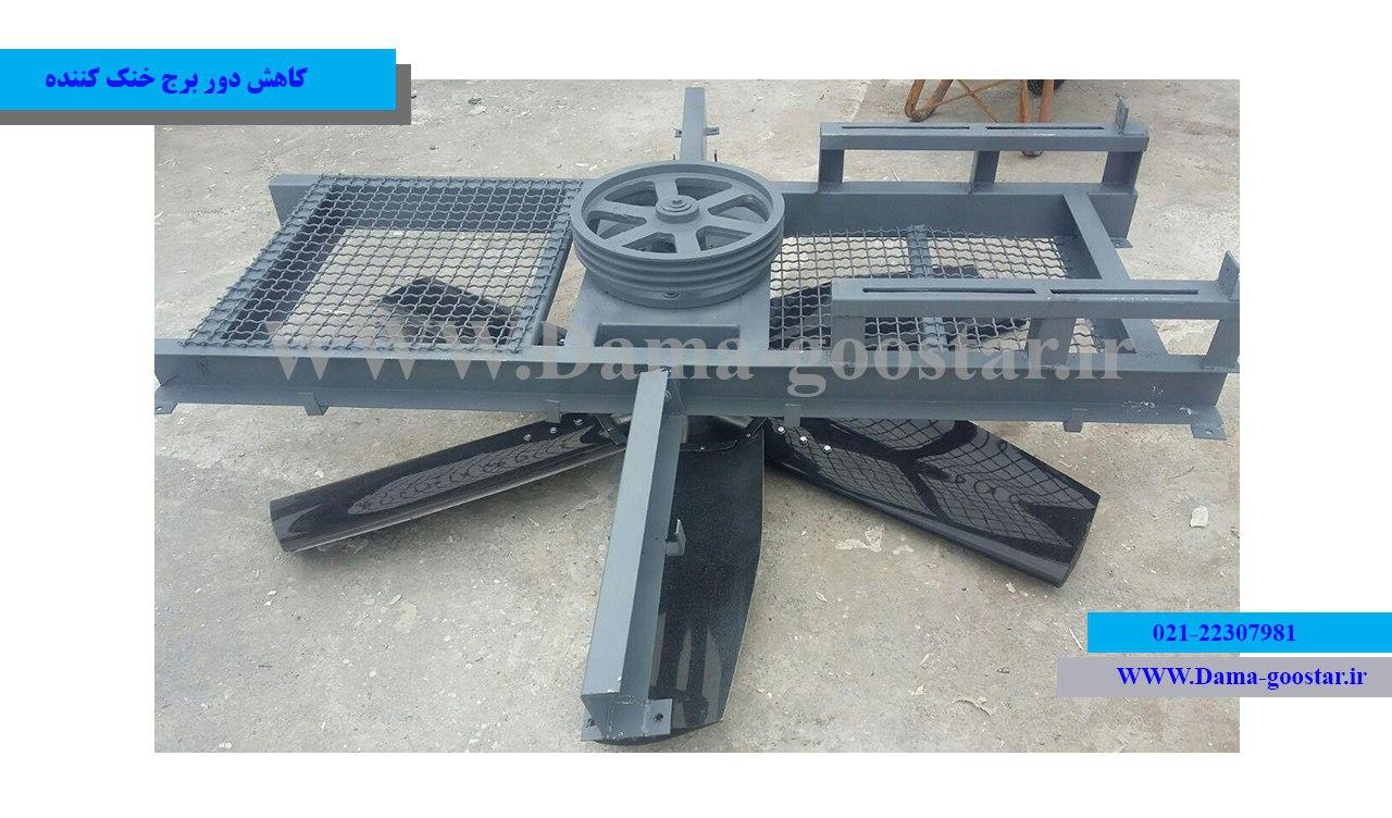
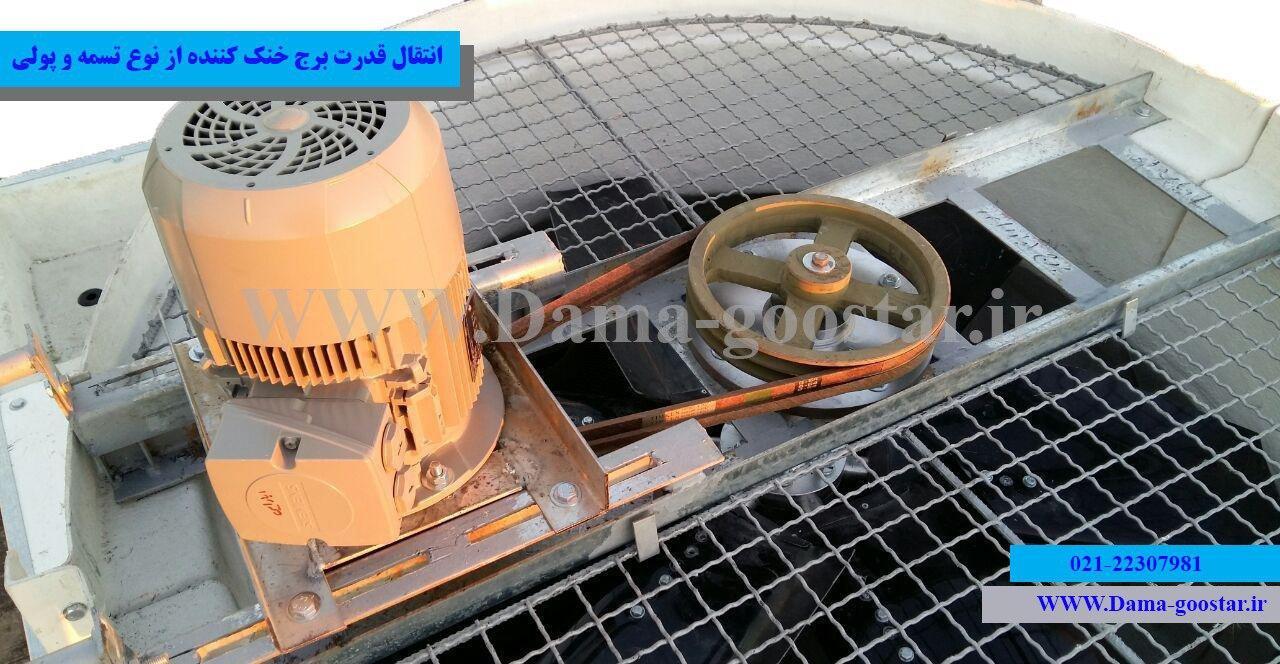
کاهش دور برج خنک کننده (Speed Reducer) وظیفه انتقال قدرت و کاهش دادن دور موتور به پروانه را برعهده دارد. کاهش دور یا اصطلاحاً کاهنده سرعت در کولینگتاور عموماً در ظرفیتهای بالا به کار برده میشود. سیستم انتقال قدرت گشتاور خروجی موتور را به فن انتقال می دهد. به دلیل چرخش سریع موتور این سیستم کاهنده، سرعت خروجی دینام را در ورودی فن کاهش میدهد. فن یا پروانه برج خنک کننده نمیتواند با سرعتهای بالا چرخش کند. به دلیل افزایش لرزش و نیروهای مقاومتی در پروانه از کاهنده دور موتور استفاده میکنیم. کاهنده دور سرعت چرخشی موتور را از 1400rpm به بازه 700 تا 200 دور بر دقیقه(rpm) تغییر میدهد. طراحی کاهش دور برج خنک کننده وابسته به پارامتر سرعت نامی فن میباشد.
کاهش دور وابسته به نوع برج خنک کننده و شرایط طراحی در انواع مختلفی طراحی و تولید میشود. برج خنک کننده یا کولینگ تاور دارای انواع مختلفی میباشد. وابسته به ظرفیت، نوع کولینگتاور(فلزی یا فایبرگلس) و قطر فنهای بکار رفته در برجخنککننده سیستم انتقال قدرت تغییر میکند. سیستم کاهنده سرعت دارای انواع مختلفی میباشد که رایج ترین آنها سیستم تسمه پولی و گیربکس میباشد. این بخش یکی از مهمترین تجهیزات سیستم هوادهی و انتقال قدرت در برج خنک کننده به شمار میآید. وظیفه سیستم کاهش دور انتقال گشتاور مکانیکی از مولد دینام به پروانه برج خنک کننده (تحت سرعت زاویهای استاندارد) میباشد.
دور:
یکی از یکاهای فیزیکی در محاسبه سرعت زاویهای در یک جسم (سرعت چرخش یک جسم) دور نامیده میشود. این پارامتر فیزیکی با یکاهایی همچون دور بر دقیقه یا rpm نشان داده میشود. rpm مخفف round per minute میباشد که معادل فارسی آن دور بر دقیقه است. این پارامتر نماینگر این است که این جسم در هر دقیقه چند بار حول یک نقطه معین 360 درجه چرخش مینماید.
سرعت نامی پروانه:
یکی از پارامترهای طراحی در سیستم هوادهی برج خنک کننده دور نامی پروانه میباشد که با توجه به قطر پروانه معین میگردد. سرعت نامی پروانههای آکسیال کولینگ تاور عموماً بین 900rpm و 200rpm در برج خنککننده طراحی میشود.
نسبت انتقال:
نسبت سرعت زاویهای ورودی پروانه یا فن به سرعت زاویهای خروجی الکتروموتور را نسبت دور یا نسبت انتقال در برج خنک کننده مینامند. این پارامتر مهم تاثیر بسزایی در طراحی قطر تسمه و پولی و یا انتخاب نوع گیبرکس دارد. تعیین نسبت کاهش سرعت مطابق فرمول زیر صورت میپذیرد.
سیستم کاهش دور و کاهنده سرعت چرخشی در کولینگ تاور یکی از مهمترین اجزا و قطعات برج خنک کننده می باشد که در بخش هوادهی و هوارسانی مشغول انجام وظیفه می باشد. اهمیت این بخش زمانی مشخص خواهد شد که با نصب اصولی و استاندارد سبب عمر پروانه و سهولت در چرخش فن خواهد گردید. کاهش دور همچنین سبب کاهش فشار و تنش به موتور به دلیل لرزش یا شدت نیروهای توربولانسی فن می گردد که این موضوع همچنین سبب عمر الکتروموتور نیز می گردد. در گاهی موارد نیز جهت اتصال غیر مستقیم پروانه به موتور از الکتروگیربکس های مخصوص با نسبت دور معین استفاده می شود.
کاهش دور در واقع تجهیزی جهت کاهش سرعت زاویه ای چرخش پروانه تا میزان استاندارد دور مناسب فن یا پروانه می باشد. سیستم کاهش دور در برج خنک کننده عموماً با استفاده از افزایش قطر پولی یا چرخ دنده متصل به پروانه سبب کاهش دور فن در کولینگ تاور می گردد. به هر میزان فن یا پروانه برج خنک کننده سایز و اندازه بزرگتری داشته باشد مطابق با قوانین فن ها باید دارای دور چرخشی یا سرعت چرخشی کمتری بوده و از این جهت نسبت قطر پولی پروانه به فولی فن نیز افزایش می یابد.
همانطور که می دانید سرعت زاویه ای یک جسم صلب در تمامی نقاط آن یکسان است. سیستم کاهش دور در اصل با افزایش شعاع چرخش یک جسم صلب سبب کاهش میزان سرعت خطی نوک دایره خواهد شد و این موضوع سبب کاهش گشتاور و در نتیجه کاهش میزان اومگا (در فیزیک واحد دور) یا دور چرخشی می گردد.
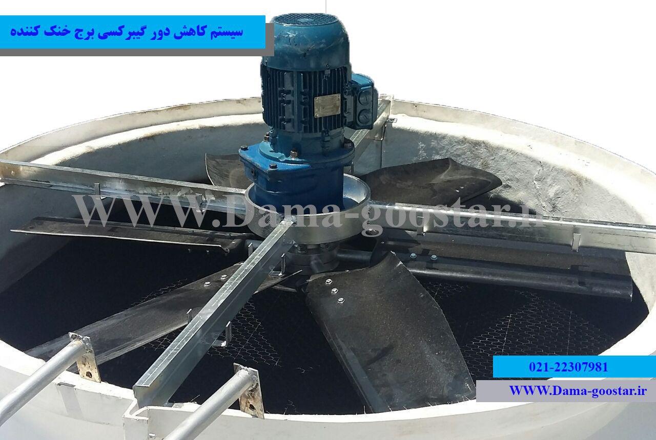
کاهش سرعت گیربکسی به صورت اتصال چرخ دنده های کوچک به چرخ دنده های بزرگ با نسبت قطر معین سبب کاهش دادن دور موتور به اندازه نسبی معین در ورودی به هاب پروانه سبب تنظیم سرعت استاندارد چرخش پروانه یا فن برج خنک کننده می شود. سیستم کاهنده تسمه ای نیز با بزرگتر کردن قطر پولی فن نسبت به فولی سر موتور سبب کاهش دور خروجی موتور در ورودی فن با نسبت دور معین می شود. هر پروانه متناسب با قطر خارجی و میزان هوادهی (Air Flow) نیازمند چرخش با سرعت زاویه ای معینی می باشد که متناسب با دور موتور برای رسیدن به دور مورد نیاز چرخش پروانه باید از سیستم انتقال قدرت یا گیربکس با نسبت انتقال مشخص استفاده نمود.
فرمول محاسبه نسبت انتقال در گیربکس و تسمه پولی: نسبت انتقال قدرت در سیستم کاهش سرعت برج خنک کننده = سرعت چرخشی موتور تقسیم بر دور پروانه یا فن کولینگتاور
به بیانی خلاصه تر با محاسبه نسبت دور در گیبرکس و تسمه پولی در واقع نسبت قطر پولی پروانه به قطر پولی یا فولی سرموتور را محاسبه نمودهایم. به عنوان مثال در سیستم فولی تسمه نوع دو تسمه با نسبت دور 1 به 3 در طراحی انتقال قدرت اگر اندازه فولی سرموتور 10 سانتی متر باشد اندازه پولی پروانه یا فن 30 سانتی متر خواهد بود.
اطلاعات بیشتر در محاسبات برج خنک کننده
در بسیاری از موارد در ظرفیت های پایین هوادهی و قطرهای کوچک پروانه، دور نامی پروانه بالاتر از 700 rpm خواهد بود که در این صورت از الکتروموتور با دور پایین (700 یا 900) به صورت کوپل مستقیم یا دایرکت درایو استفاده می شود. این بدین معنی است که از شافت موتور مستقیماً جهت چرخش پروانه استفاده می شود که در این حالت دور یا سرعت چرخشی پروانه با دور موتور برابر خواهد بود. در انواع برج خنک کننده با ظرفیت پایین تر از 60 تن تبرید عموماً سیستم انتقال قدرت به صورت کوپل مستقیم (Direct Drive) می باشد.
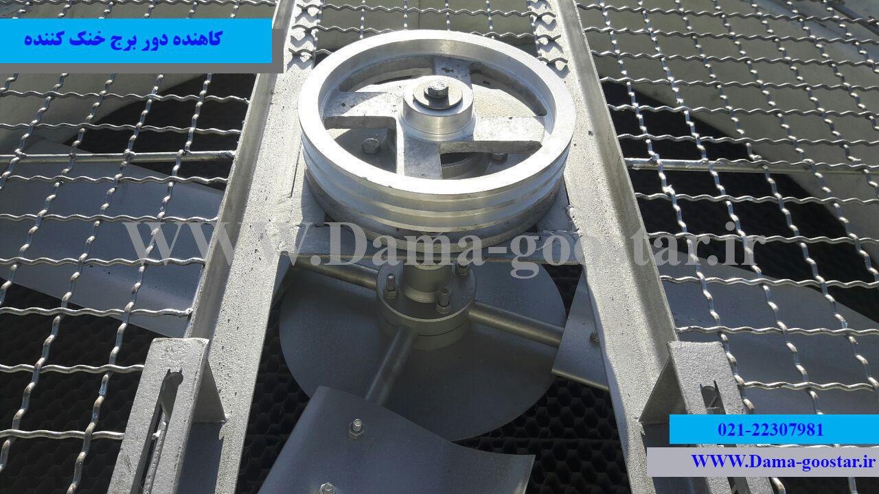
سیستم انتقال قدرت تسمه و پولی یا تسمهای
کاهنده دور تسمه ای یا تسمه و پولی شامل سه بخش اصلی می باشد. بخش یا قسمت اول فولی یا پولی سر پروانه می باشد که از یک محور یا شافت ، بلبرینگ و قسمت تسمه خور تشکیل می شود. بخش دوم پولی سر موتور می باشد که دارای یک جا شافتی جهت اتصال به شفت موتور می باشد. بخش سوم تسمه می باشد که از گریدهای مختلف و سایزهای مختلف در انواع سیستم کاهش دور تسمه ای در برج خنک کننده استفاده می شود.
سیستم کاهش دور گیبرکسی
روش انتقال قدرت باگیربکس در برج خنک کننده یکی از رایج ترین انواع سیستم کاهنده دور مورد استفاده در بخش هوادهی کولینگ تاور می باشد. گیربکس یا جعبه دنده مجموعه ای متشکل از دنده های فلزی می باشد که دنده کوچکتر به شافت موتور و دنده بزرگتر همیشه به هاب پروانه اتصال می یابد. گیربکس های به کار رفته در برج خنک کننده به عنوان یک سیستم کاهش دور عموماً دارای دو مشخصه اصلی می باشند. در انتخاب گیربکس برج خنک کننده ابتدا باید دور نامی فن یا پروانه را در قطر آن محاسبه نمود سپس با استفاده از دور ورودی موتور و توان موتور گیربکس را انتخاب نمود.
پنج گام اساسی در انتخاب سیستم کاهش دور برج خنک کننده
محاسبه توان الکتروموتور یا مولد مکانیکی در تأمین گشتاور مورد نیاز جهت چرخش پروانه
تعیین و مشخص نمودن دور نامی (سرعت چرخشی نامی) یا استاندارد فن یا پروانه در کولینگ تاور
محاسبه نسبت دور یا دور خروجی با استفاده از دور نامی مطابق فرمول ذکر شده
نوع سیستم هوادهی (آکسیال یا سانتریفوژ) و محاسبه فشار دینامیکی و استاتیکی مورد نیاز فن
نوع برج خنک کننده یا کولینگ تاور و جهت عبور جریان هوا و انتخاب نوع گیبرکس یا تسمه پولی با توجه به شرایط طراحی
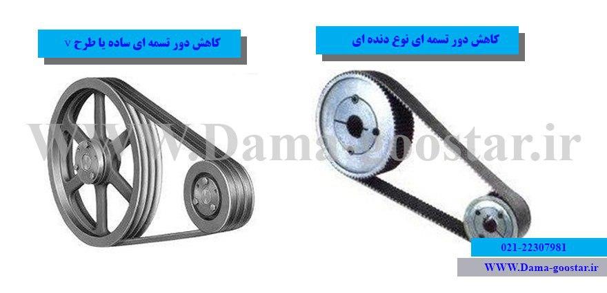
کاهش دور تسمهای طرح V ساده
کاهنده دور نوع تسمه ساده (V belt) پرکاربردترین نوع کاهنده تسمه و پولی می باشد که تسمه های این مدل با دو نوع عرض کوتاه b و عرض زیاد a مورد کاربرد قرار می گیرد. تسمه نوع b بیشترین کاربرد را در انواع برج خنک کننده دارد . سایزهای تسمه b54 و b65 و سایزهای بزرگتر عموماً در سیستم های کاهش دور دو تسمه، سه تسمه و بالاتر مورد کاربرد قرار می گیرد.
کاهش سرعت تسمهای دندانه دار
کاهش دور تسمه ای دنده دار بیشتر در موتورهای بسیار قوی همانند موتور ماشین (تسمه تایم) به کار برده می شود. بیشتر ماشین آلات صنعتی که از موتورهای بسیار قوی با گشتاورهای بالا استفاده می کننده از سیستم کاهنده دور دنده ای جهت انتقال قدرت بین اجزا مختلف خود استفاده می نمایند.
کاهندههای تسمهای عموماً به دلیل چرخش محور موتور حول افق فقط تحت تنشهای کششی ناشی از چرخش محور موتور قرار میگیرد. این نیروی کششی و ضربه زننده توسط موتور عمدتاً توسط هرزگرد یا بلبرینگ چرخان دمپ میگردد. در واقع هرزگرد در نقطه مقابل فولی موتور قرار میگیرد و نیروهای کششی حول محور ساعتگرد موتور را طی یک چرخش مع دفع مینماید. هرزگرد برج خنک کننده مزیتهای بیشماری در کارکرد کولینگ تاور خواهد داشت که مهمترین آنها عبارتند از:
مهمترین مزایای استفاده هرزگرد در سیستم انتقال قدرت برج خنک کننده
افزایش طول عمر بلبرینگ در قسمت پولی پروانه یا فن
عمر موتور با کاهش نیروی وارد بر شفت
کاهش میزان سطح ارتعاشات حاصل از انتقال قدرت موتور به پروانه
کاهش میزان سطح دسیبل صدای تولیدی کولینگ تاور
تسمه ها در دو نوع کلی دندهدار و ساده تقسیم بندی میشود. تسمههای ساده در سیستم انتقال قدرت تسمه پولی کاربرد بیشتری دارند. با توجه به سرعت چرخش پایین فن یا پروانه نوع دندهدار کاربردی ندارد. تسمه نوع دندهدار اکثراً در موتورهای صنعتی مثل موتور خودرو کاربرد دارد. تسمه تایم یکی از رایجترین انواع تسمه دندهدار میباشد. تسمه نوع V یا همان تسمه ساده خود به دو دسته معمول A و B تقسیم میشود. تفاوت بین تسمههای مختلف در عرض آنها میباشد. عرض تسمهها هر چه حروف به A نزدیک میشود باریکتر می شود. تسمه های نوع b در برج خنک کننده کاربرد بیشتری دارد.
تسمه های بکار رفته در کولینگ تاور معمولاً از نوع b میباشد. به دلیل استفاده از فولیهای پروانه بدون دندانه نوع تسمه ها ساده میباشد. قدرت و قوام تسمه وابسته به تعداد لایههای بکار رفته در ساخت تسمه متفاوت می باشد. تسمههای کرهای از کیفیت بیشتری در مقابل سایر برندها برخوردار است. تسمههای اندونزی، تایوان و چین نیز در ردههای بعدی کیفی تسمهها قرار دارد. نوع تسمه تأثیر بسیاری بر کارکرد صحیح سیستم انتقال قدرت تسمهای دارد. تسمه پروانه های بکار رفته در کولینگ تاورهای دما گستر از نوع کره ای با روکش مخصوص میباشد.
درباره این سایت